
PLC Technology LLC manufactures a wide range of remote control devices. The devices offer an optimal solution for any type of substation, taking into account various features of primary equipment and different operation environments.
PLC Technology LLC manufactures a wide range of remote control devices. The devices offer an optimal solution for any type of substation, taking into account various features of primary equipment and different operation environments.
The main purpose of remote control of distribution networks is to collect and process operation mode data of the electrical equipment at the controlled site and transmit the remote control data from the automation object to upper levels.
The remote control system for distribution networks ensures the following:
1. Better visibility of technical processes;
2. More reliable data transmission;
3. Higher reliability and efficiency of process control;
4. Reduced number of emergency situations;
5. Reduced equipment operating costs.
Based on their architecture, remote control systems can be categorized as follows:
1. Distributed
2. Centralized
In distributed architecture, the site condition data are collected using bay controllers installed in the connections under control.
Data from bay controllers are aggregated and transmitted to upper control levels by the remote station, which consists of the TOPAZ IEC DAS MX240 data access server (controller) and a power supply system.
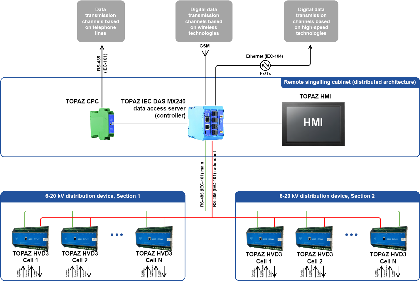
Figure 1. Diagram of the distributed architecture of a remote control system
Remote control devices—TOPAZ bay controllers of the HVD3 series—are installed in low-voltage cell sections of single-end service assembled chambers, switchgears, and gas-insulated monoblocks. The devices directly collect and process discrete signals, issue control commands as well as all measurements and calculations related to network parameters.
We offer different modifications of these devices depending on the volume of the remote data under control:
TOPAZ HVD3-RTU1 performs the functions of remote signaling, remote control, and phase control;
TOPAZ HVD3-RTU3 performs the functions of remote signaling, remote control, phase control, and remote measurements of the load current in one phase;
TOPAZ HVD3-RTU5 performs the functions of remote signaling, remote control, phase control, and remote measurements of current and voltage in three-phase three-wire and four-wire AC networks as well as measurements of active and reactive AC power;
TOPAZ HVD3-RTU7 performs the functions of remote signaling, remote control, phase control, and remote measurements of current and voltage in three-phase three-wire and four-wire AC networks, zero sequence current measurements as well as measurements of active and reactive AC power;
TOPAZ HVD3-EM3 performs the functions of remote signaling, phase control, and remote measurements of current and voltage in three-phase three-wire and four-wire AC networks as well as measurements of active and reactive AC power.
The TOPAZ IEC DAS MX240 data access server (controller) collects data from bay connectors and transmits it to higher control levels. It also performs integration with related systems via open transmission protocols (IEC 60870-5-104, IEC 60870-5-101, Modbus RTU, etc.).
Discrete and analog information signals for transmission to the upper level are created either sporadically (signals of discrete values are created upon value changes, while signals of analog values are created using the aperture method) or in a cyclical manner (by global polling on a predetermined periodic basis).
Using the IEC 60870-5-104 protocol for remote control exchange makes it possible to transmit remote control data with a timestamp.
The TOPAZ IEC DAS MX240 controller is a module-based device—the number and type of interfaces (electrical/optical Ethernet, RS-485) for transmitting the device's data depend on the specific device configuration and availability of the respective extension boards.
In addition to interface boards, the controller may include functional boards:
· PTS for clock synchronization based on GLONASS/GPS radio signals
· GSM for establishing communication links based on mobile operator networks
· HMI for creating the human-machine interface (operator board).
The controller is designed in the form of a plastic case for DIN rail mounting.
The data access server communicates with the bay controllers by means of the redundant RS-485 digital interface via the IEC 60870-5-101 protocol.
The distributed architecture makes it possible to minimize the amount of cabling and the size of the remote station, which is important in the restricted space of the substation.
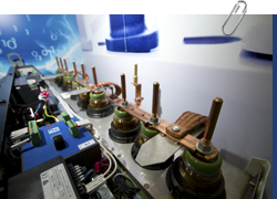
In the centralized architecture of the automated remote control system, the remote station is the only device that performs the functions of status control and management.
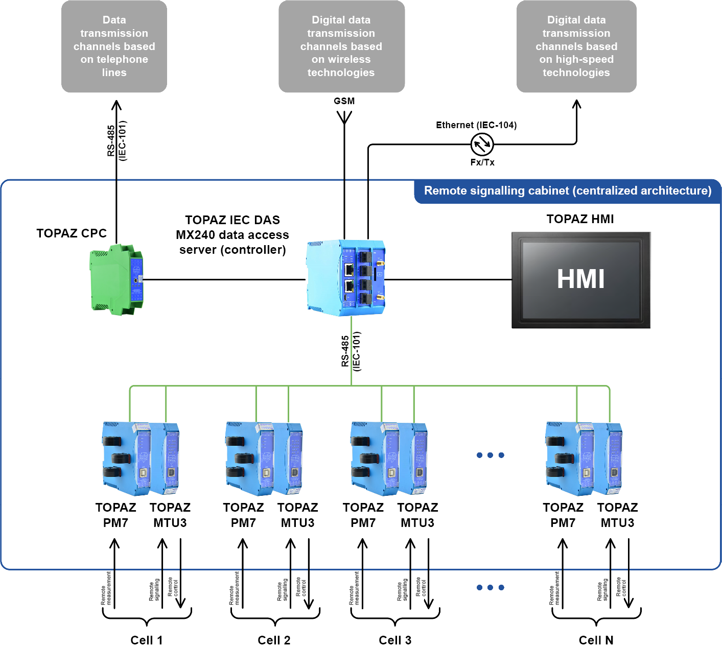
Figure 2. Diagram of the centralized architecture of a remote control system
In this architecture, the remote station is a cabinet that contains the data access server, discrete signal input/output modules, digital measurement converters, and the power supply system.
To meet the requirements of this type of remote control architecture, PLC Technology LLC has developed TOPAZ ТМ MTU3-Pr or TOPAZ ТМ MTU5-Pr remote control modules as well as the TOPAZ TM PM7-Pr product line of multifunctional measurement converters.
TOPAZ ТМ MTU3-Pr or TOPAZ ТМ MTU5-Pr remote control modules are used for discrete signal input and output of discrete control signals.
TOPAZ ТМ MTU3-Pr performs the functions of remote signaling, remote control, and phase control;
TOPAZ ТМ MTU5-Pr performs the functions of remote signaling, remote control, and phase control;
TOPAZ TM PM7-Pr multifunctional measurement converters are used to measure electric network parameters. We manufacture a range of modifications depending on the required functions.
TOPAZ ТМ PM7-Pr
Inside the remote station cabinet, a T-Bus is used to connect modules, supply power to each module, and create interface links.
Thanks to this architecture, no additional connections are required for operation of a module. This reduces the amount of cabling inside the cabinet and simplifies the equipment installation.
To protect the system against voltage depression of the power supply network, uninterruptible power supply of the remote control system equipment is ensured.
There are several options for implementing the uninterruptible power supply:
1.The TOPAZ MRP-220V24V2A uninterruptible backup power supply module should be used for remote stations with a single power terminal.
This module is designed for uninterruptible power supply to 24 VDC equipment.
The module ensures uninterruptible automatic switching of power supply for its connected consumers from the main power supply input to the backup input and vice versa in the event of power outage, or when voltage parameters go beyond the determined threshold values.
The module is used together with the TOPAZ AU 7AH/12V accumulator unit, and the maximum power it can supply to consumers is 50W.
Figure 3. Diagram of the backup power supply using the TOPAZ MRP-220V24V2A module
2. The TOPAZ PSC 24V10А power supply control module is used for remote stations with two power terminals.
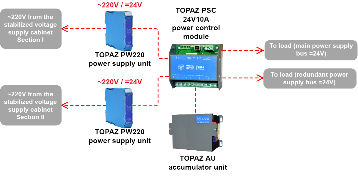
Figure 4. Diagram of the backup power supply using the TOPAZ PSC 24V10А module
The TOPAZ PSC 24V10 power supply control module performs the following functions:
· monitors the availability of voltage in input and output voltage channels;
· switches to backup or emergency power sources for external devices if no voltage is available in the main input voltage channel;
· monitors the battery charge level and, if the charge level drops below a preset value for the module, connects the battery to a power source;
· monitors the ambient air temperature and, if necessary, supplies power to the cable heating system.
The TOPAZ PSC 24V10А power control module is used together with TOPAZ AU; 24 V accumulator units of various capacity, depending on the required battery operation time. The maximum power it can supply to consumers is 240 W.
All the remote control functions of the system are implemented using the equipment included within a single TOPAZ software and hardware system.
As a result, it becomes possible to:
1. Minimize costs related to personnel training—they are trained to use the software and hardware system as a whole, not just its individual components;
2. Minimize spare parts, tools, and equipment—only unified components are used to build a system;
3. Avoid dependency on imported equipment—the TOPAZ software and hardware system is a domestic product;
4. Eliminate issues regarding compatibility of system components and regarding the manufacturer's liability in case of failures;
5. Perform diagnostics of interface connections, the power supply system, and individual system components.
