
Conventional current meters based on current transformers have a considerable weight and size, particularly for high voltage circuits. This leads to high material costs and excess amounts of time spent on manufacturing, installation, and operation. The issue is further complicated by the strict fire safety and electrical safety requirements that exist for such devices. Using electrical current transformers also leads to significant electrical power losses.
An alternative to using electrical current transformers as primary transducers are fiber-optic current transformers or optical current transformers. The emergence of these transformers is a result of huge advances in fiber-optic technology as well as in the development and manufacturing of compact and stable semiconductor lasers, optical receivers, and magnetically sensitive optical materials.
The key issue when using electrical current transformers is ensuring insulation between the measuring instruments and HV circuits. This does not affect optical current transformers as the current values are measured by dielectric fiber-optic lines and an optical current sensor. For the same reason, devices that use optical current transformers are highly resistant to external electric and magnetic interference and are much smaller and lighter.
In using advanced fiber-optic lines with low attenuation per unit of length, it is possible to position the Rx/Tx module at a large distance from the line being measured. The distance between an optical current sensor on the line being measured and an Rx/Tx module can be as high as several kilometers.
There are a range of optical current meter designs available. Most optical current meters operate as follows (figure 1): polarized radiation is delivered by an optical waveguide to a magnetically sensitive sensors, where the light polarization is modified under the magnetic field induced by the measured current (Faraday effect). Then, the waveguide carries the radiation to an analyzer that detects the change in radiation polarization. A photo detector converts the optical signals into electrical ones. A digital processing unit amplifies the electrical signals as required and operates as an ADC. A microcontroller decodes and processes the discrete code to produce absolute current values to be sent to the external interfaces.
Conventional photo emitters are based on LEDs and laser diodes with a fiber-optic single-mode or multimode output. The most commonly used magnetically sensitive elements are optical elements with a high Verdet factor (this indicates the light polarization plane rotation in a magnetic field). Most meters can be divided into two groups: meters with a fiber sensor and meters with an optical crystal sensor. The sensors in the first group are made of a special optical fiber that forms a multiturn loop around the conductor with the current being measured. The sensors in the second group are magnetically sensitive crystals located directly on the conductor with the current being measured. Birefringent prisms or polarized films are used as a polarizer and an analyzer. Photodetectors are based on pin diodes with fiber-optic radiation inputs. See figure 1 for the block diagram of the proposed three-channel optical current meter. The optical current sensor used is a rare-earth garnet ferrite crystal positioned between the polarizer and the analyzer. The optical sensor in a dielectric enclosure is attached to a cable and secured with two clamps (figure 2).
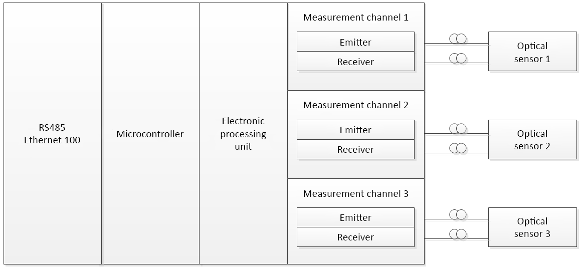
Figure 1. Block diagram of the proposed optical current meter
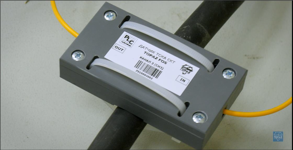
Figure 2. External view of the optical current sensor attached to an electric cable
Laser radiation emitted by the near IR semiconductor laser is transmitted over a single-mode fiber to the optical current sensor and then to the photo receiver, which converts the optical signal into an electric one. Then, the electric signal is amplified and converted into a digital signal for subsequent digital processing.
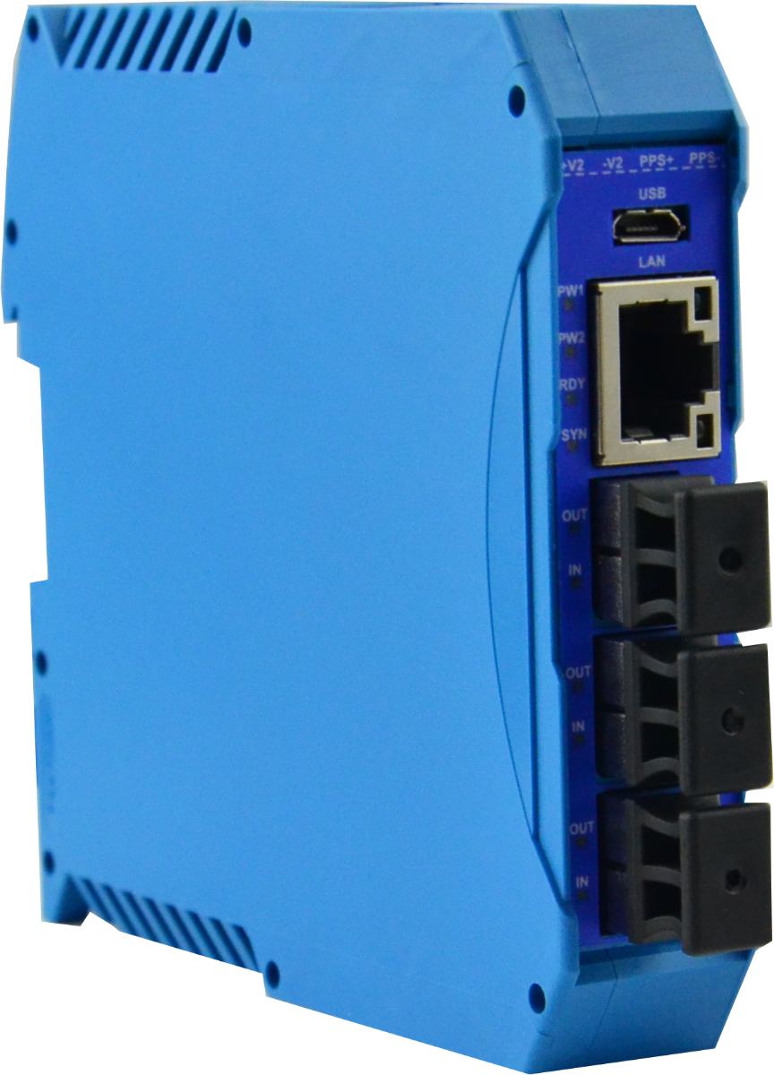
Figure 3. External view of the optical current meter
Key benefits of the current monitoring system:
· Compact size, making it possible to mount the hardware into existing racks
· Powerful laser source, which makes it possible to install sensors in cable line transposition chambers at least 10 km away from the installed module location
· Passive sensors that do not require electric power
· Application at digital substations
Table 1 -- Device specifications
|
Feature |
Value |
|
Current measurement channels |
|
|
Number of channels: |
3 |
|
Type of current sensor interface ports |
LC (single-mode fiber) |
|
Max fiber-optic line length, km |
up to 5 |
|
RMS current, A |
up to 1,000 |
|
Frequency, Hz |
30–3,000 |
|
Ethernet communication interface |
|
|
Baud rate, Mbit/s: |
10/100 |
|
Connector type |
RJ-45 |
|
Data exchange protocols |
IEC 60870-104; SV 61850-9-2 (optional) |
|
RS-485 communication interface |
|
|
Baud rate, bit/s: |
up to 115,200 |
|
Data exchange protocol |
IEC 870-5-101 |
|
Power supply |
|
|
Rated supply voltage, V |
24 (DC) |
|
Rated supply voltage range, V |
9 ÷ 58 |
|
Current (at 24 V), mA |
100 |
|
Structure |
|
|
Mounting type |
DIN rail 35 mm |
|
Case |
IP 20 plastic |
|
Module dimensions (width х height х depth), mm |
22.5 x 99 x 117 |
|
Mass, kg: |
0.5 |
|
Operating conditions and reliability |
|
|
Operating temperature range, 0 |
-40 to +70 |
|
Mean time between failures, h |
140,000 |
|
Average service life, years |
30 |
