
The vibroacoustic monitoring system (SVAM) is designed to ensure timely detection of potential threats to a guarded site and to provide information about the impact location and type to an upper level. It is installed at extended linear objects (cable lines, high-voltage lines, oil and gas pipelines) and along perimeters of guarded objects.
Key benefits of SVAM:
· Option to use it as a distributed fiber sensor at already completed fiber-optic links
· Ready-to-use library of events for fast equipment commissioning
· Determining geodesic coordinates of an event for quick response
· Smart processing algorithms to minimize false triggering
· In the case of installation on high-voltage lines, the SVAM can be optionally equipped with a thermal control system for glaze melting
· Compact size (3U), making it possible to mount the hardware into existing racks.
· Application at digital substations.
The SVAM uses the Rayleigh laser beam scattering effect in a distributed optical environment.
The distributed optical environment is the G.652/G.654 single-mode optic fiber.
Theoretically, scattering takes place at each point on the laser beam route via optical fiber, and some of the energy goes back.
This is typical for the Rayleigh backscattering when the reflected signal phase depends on local disturbances (acoustic impacts, vibrations) at each point (figure 1):
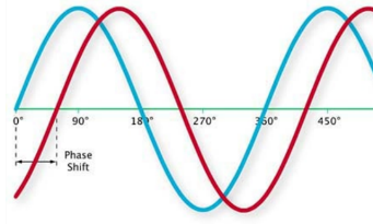
Figure 1. Dependency of the reflected signal phase on local disturbances
Therefore, an optical sensor measuring the Rayleigh backscattering can determine the vibroacoustic impact for each point of optical fiber within its resolution range. The distance to the vibroacoustic impact is determined by the time of signal arrival. This algorithm is illustrated in figure 2.
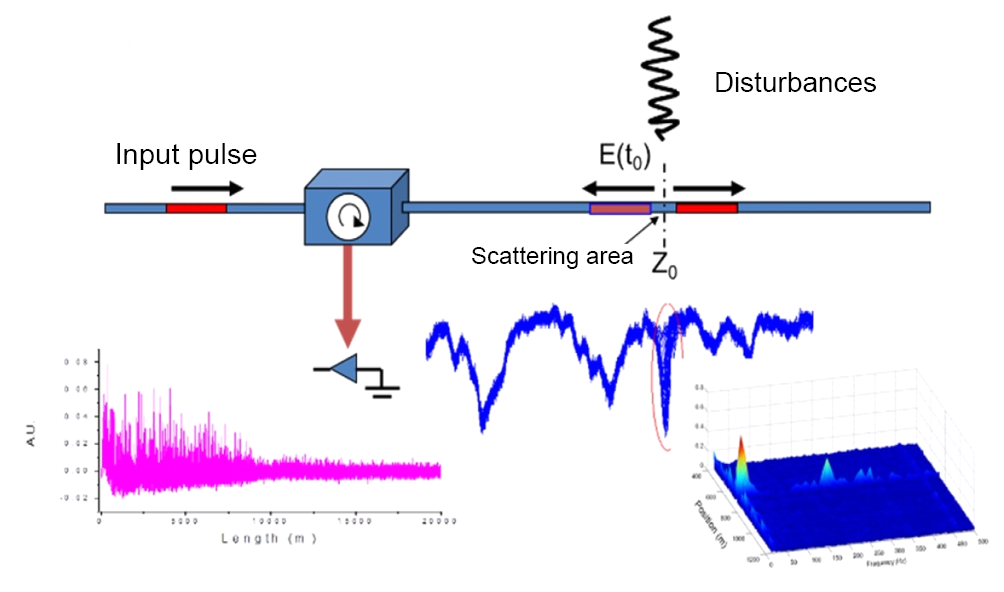
Figure 2. Algorithm for determining the vibroacoustic impact
The SVAM registers impacts within the frequency range of 1 Hz–2.5 kHz.
Sampling resolution up to 5 m. This resolution range is sufficient for reliable recording of vibroacoustic events within several dozens of meters on either side of the distributed sensor location.
The meter consists of an ultra narrowband laser source and a photoelectric sensor. The photoelectric sensor performs digital conversion and saves the resulting data array to the device's nonvolatile memory. In fact, the data array is digital sound within the 1 Hz–2.5 kHz frequency range and sampling dimension of 5 m. If necessary, the data array can be saved to an external medium for further analysis and playback.
The data array is converted in the nonvolatile memory of the device using recognition algorithms. The recognition algorithms are based on an event template library. At present, the library contains templates for all types of events that may be regarded as unauthorized activities within the guarded area of the aerial cable line. These events include operation of heavy vehicles (e.g., excavator), drilling, and many others.
The recognition algorithms have a multilevel structure. At the first level, the event type is determined at a specific point, for example, "single digging has been recorded". If digging is repeated several times within a certain time period (configurable), these events form the "manual digging" process at the next level. If the "manual digging" process continues for a certain period of time (e.g., 30 minutes of digging for a cable line at a depth of 2 m, as it was experimentally observed), recognition at the next level issues the "dangerous manual digging" alert. This alert is issued in order to respond to such an event.
The recognition algorithms are implemented in an individual computing unit that operates jointly with the vibroacoustic monitoring device.
The results are displayed in the form of a map on which the respective aerial cable line is drawn. Each recognized signal has geodesic coordinates and is visualized on the map.
The distributed sensor is a single-mode optical fiber both in a power cable or individually laid. Bearing in mind that most cable lines do not have built-in single-mode optical fiber, the external optical fiber is generally used.
We advise to use the optical fiber of a fiber-optic link installed close to the power cable.
The resulting standard diagram of the vibroacoustic monitoring system is shown in figure 3.
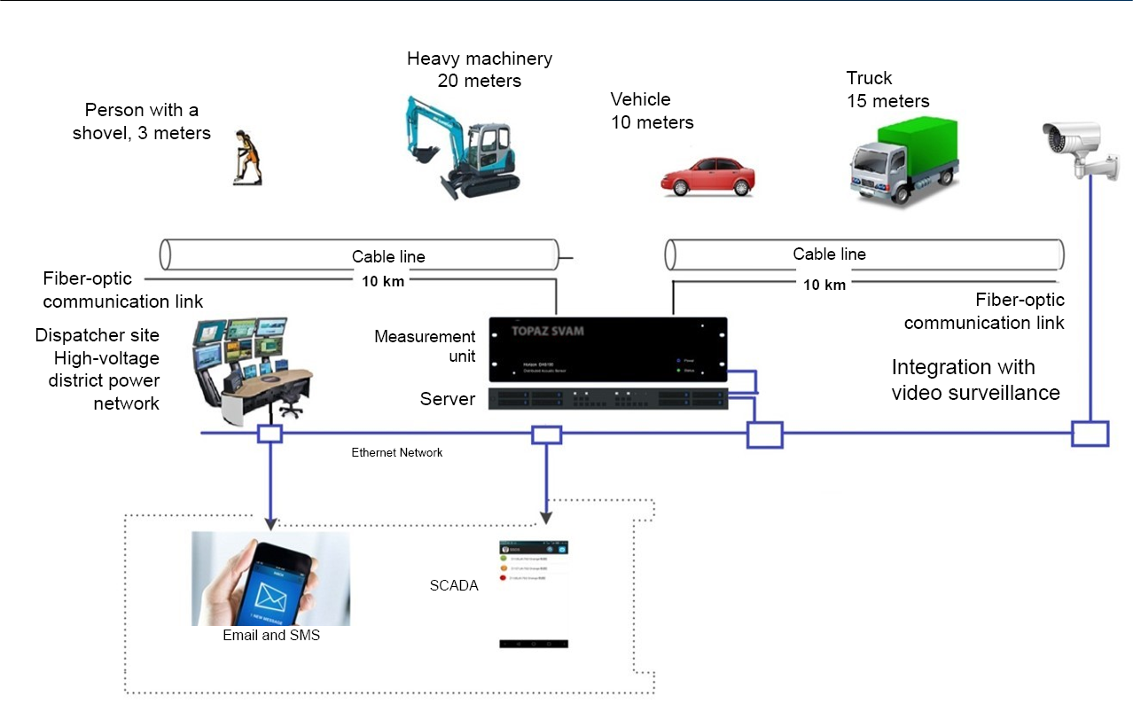
Figure 3. Standard SVAM diagram for cable lines
The TOPAZ SVAM measurement device for vibroacoustic monitoring and the server are installed at a substation. Taking into account the TOPAZ SVAM and the server form factors (3U and 2U, respectively), the equipment can be mounted in an existing rack.
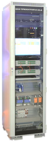
Figure 4. External view of the SVAM rack
The operation requires laying a patch cord to the communications room where switching is performed at the terminal box with the optical fiber with the most suitable attenuation level.
To perform commissioning, the cable line laying plan is required. The plan must specify the depth, laying type, and intersections of the cable line route with acoustic impact sources.
The cable route plan is plotted on the map base and linked to it with respect to acoustic impact sources. Then, the map, which is the map base with the plotted cable laying plan, becomes available for the software installed on any required number of automated workplaces at different locations. When an event occurs, the vibroacoustic monitoring system generates an alert signal with coordinates for the respective event type. Once the signal is received, the event is visualized on the map at the automated workplace.
If several events occur at different locations, all of them are visualized.
The layout is shown in figure 5.

Figure 5. Screen of the automated workplace software
During commissioning, the cable line laying plan is divided into areas on the map. A noise reduction coefficient is set for each area, so is the monitoring distance to the left and to the right for recording, trigger types (templates for event recording). The SVAM specifications are listed in table 1.
Table 1. SVAM specifications
|
Normal operating conditions, ambient air temperature, °C |
-40 to +70 |
|
Normal operating conditions, relative air humidity (noncondensing), % |
5 ÷ 95 at 30 °C |
|
Normal operating conditions, atmospheric pressure, hPa |
60 to 106.7 |
|
Division into fully configurable independent areas |
More than 1,000 |
|
Ready-to-use event library |
Available |
|
Optical fiber type of the distributed sensor |
SM (single-mode) G.652/G.654 |
|
Maximum length of the distributed sensor, km |
up to 100 |
|
Precision of the detected event location, m |
+-5 |
|
Average event registration time, s |
+-5 |
|
Frequencies for event recording, Hz |
1–2,500 |
|
Operation mode setup time, min, max. |
10 |
|
Optical connectors |
FC/APC |
|
Emission sources wavelength, nm |
1,550 |
|
Operation mode |
Continuous |
|
Moving parts |
None (uses fanless technology) |
|
Interfaces |
RS232, RJ45 |
|
Data exchange protocol |
IEC 61850-8-1 MMS, IEC 61850-8-1 GOOSE, IEC 60870-5-104, DNP3, Modbus TCP, IEC 60870-5-101, Modbus RTU, SNMP v1/v2/v3 |
|
Communication redundancy protocols |
RSTP, PRP, HSR |
|
Database interaction technology |
Client–Server |
|
Time period for storing vibroacoustic data, months |
Min. 3 |
|
Power supply voltage, V |
100÷240 АС |
|
AC voltage frequency, Hz |
45÷60 |
|
Power consumption, W, max.: |
25 |
|
Autonomous operation time, h, min. |
8.5 |
|
Average service life, years |
30 |
