


| Feature | Value |
|---|---|
| Telemetering channels | |
|
Number of current metering channels |
4 |
|
Rated value of metered current (Ia, Ib, Ic), A |
1; 5 |
|
Current metering range, A |
0.01 ÷ 1.5Irat |
|
Maximum value of metered current (Ia, Ib, Ic), A |
7.5 |
|
Metering range of zero sequence current 3Io, A |
0.01 ÷ 5 |
|
Maximum amperage 3Io, A |
15 |
|
Power consumption of current circuits in nominal mode (for each phase), VA, max. |
0.3 |
|
Number of voltage metering channels |
3 |
|
Rated value of metered alternating voltage (phase/linear), V |
57.7 / 100; 230 / 400 |
|
Phase voltage metering range, V |
0.3 ÷ 1.2Urat |
|
Power consumption of voltage circuits in nominal mode (for each phase), VA |
0.1 |
|
Verification frequency, years |
10 |
| Telesignaling channels | |
|
Number of channels |
8–40 |
|
Discrete input channel input voltage, V |
5 ÷ 220 |
|
Maximum input voltage, V |
350 |
|
Input impedance, kOhm |
0.5 ÷ 220 |
|
Rated value of input currents, mA |
1 ÷ 10 |
| Telecontrol channels | |
|
Number of channels |
up to 16, depending on the version |
| Ethernet interfaces | |
|
Ports |
up to 8 |
|
Baud rate, Mbit/s |
up to 100 |
|
Design variants |
RJ-45, LC (single-/multi-mode), SFP |
|
Data exchange protocols |
IEC 60870-5-104, IEC 61850-8-1 (option) |
|
Network redundancy protocols |
PRP |
|
Clock synchronization protocol |
IEC 60870-5-104, PTP |
| RS-485 interface | |
|
Ports |
up to 3 |
|
Baud rate, bit/s: |
up to 115,200 |
|
RS-485 interface communication protocol |
IEC 870-5-101, Modbus RTU |
| Power supply | |
|
Power supply voltage, V - LV version - HV version |
15 ÷ 30 90 ÷ 264 |
| Design | |
|
Case |
IP 20 plastic |
|
Mounting |
DIN rail 35 mm |
|
Overall dimensions (WxHxD) |
depending on the version |
|
Weight, kg, max |
1 |
| Reliability | |
| Mean time between failures, h | 140,000 hours |
|
Average lifetime |
30 years |
| Operating environment | |
|
Ambient air temperature, °С |
-40 to +70 |
|
Relative humidity (non-condensing), % |
5 ÷ 95 at 30 °C |
|
Air pressure, kPa |
60 ÷ 106.7 |
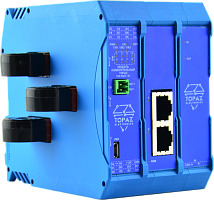
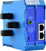
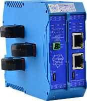
| TOPAZ TM PM7–A-[B1- to -Bx]-[C]-[D1- to -Dx]-[E1-to -Ex]-[F]-[G]-[K]-[L]-M-Pr | ||
| Position | Code | Description |
| Modification (set of functions) | ||
| A | W | Measurement of electric parameters. Electricity metering. |
| E | Measurement of electric parameters. Electricity metering. Basic electricity quality indicators based on GOST 32144-2013. Oscilloscope record. Detection of short circuits and steady-state line-to-ground faults. | |
| D | Measurement of electric parameters. Electricity metering. Detection of short circuits, steady-state and alternating line-to-ground faults. | |
| Q | Measurement of electric parameters. Electricity metering. Power quality indicators (full list). | |
| LW | Measurement of electric parameters. Option to power the device using voltage measurement circuits. | |
| Ethernet communication ports | ||
| В1 to Bx | nGTx | Ethernet 1000 Mbit/s TX RJ45 |
| nGSFP | Ethernet 1000 Mbit/s SFP | |
| nGTXSFP | Ethernet 1000 Mbit/s combo-port RJ45/SFP | |
| nTx | Ethernet 100 Mbit/s TX RJ45 | |
| nFxS | Ethernet 100 Mbit/s FX LC single-mode | |
| nFxM | Ethernet 100 Mbit/s FX LC multi-mode | |
| n – number of Ethernet ports of the respective type | ||
| RS-485 communication ports | ||
| C | nR | RS-485, where n is the number of ports |
| Discrete inputs/outputs | ||
| D1 to Dx | nDI | Discrete inputs, where n is the number of discrete inputs. Increment – 8. |
| nDOS | Discrete outputs of the signal relay type, where n is the number of discrete outputs. Increment – 8. | |
| nDOC | Discrete outputs of the control relay type, where n is the number of discrete outputs. Increment – 3. | |
| Design based on analog measurement circuits | ||
| E1 to Ex | UI | Fixed set of analog channels |
| nU | AC voltage measurement channels | |
| nUDC | DC voltage measurement channels | |
| nIMC | AC measurement channels with a range of up to 50A | |
| nIPC | AC measurement channels with a range of up to 200A | |
| nEMC | AC measurement channels with remote sensors and extended range of up to 50A | |
| nEPC | AC measurement channels with remote sensors and range of up to 200A | |
| nEPCО | AC measurement channels with remote connector sensors and extended range of up to 200A | |
| Design variants based on analog measurement circuits can be found in the table below | ||
| Information exchange protocols (in addition to basic protocols) | ||
| F | IEC81 | IEC 61850-8-1 |
| G | PRP | PRP redundancy protocol support |
| Real-time clock | ||
| H | RTC | Non-volatile real-time clock |
| Additional options | ||
| I | SSDm | SSD drives, where m is the total ROM volume of SSD drives in gigabytes (terabytes) |
| SSDmT | ||
| J | GNS | Built-in GPS/GLONASS reciever |
| K | GSM | Built-in GSM modem |
| L | PAN | Design variant with a built-in indicator for integrating into a panel |
| Built-in power supply | ||
| M | LV | One power supply input Urat = 24V DC |
| 2LV | Two power supply inputs Urat = 24V DC | |
| HV | One power supply input 220V DC/AC | |
| 2HV | Two power supply inputs 220V DC/AC | |
Module design variants based on analog measurement channels
| Design version | Set of measurement channels | Supported modifications |
| Basic design variant with a fixed set of analog channels | ||
| UI | 3 AC voltage measurement channels with a common neutral wire |
PM7-W, PM7-E |
| 3 channels of phase current measurement; built-in measurement current transformer | ||
| Current measurement channel for connecting an external core balance current transformer | ||
| Design variants with a custom set of analog channels | ||
| 4U-4IMC |
4 alternating voltage channels, 4 alternating current channels |
PM7-D, PM7-Q |
| 4U-4IPC | ||
| 4U-3IPC-1IMC | ||
| 4U-4EMC | ||
| 4U-4EPC | ||
| 4U-3EPC-1EMC | ||
| 4U-4EPCO | ||
| 3U-1EMC |
3 alternating voltage channels, 1 alternating current channel |
PM7-LW |
| 3U-1EPC | ||
